
For decades, one of the most persistent assumptions in exterior wall design has been simple: a larger drainage gap should provide better drainage.
The reasoning appears intuitive. If water penetrates behind exterior cladding, a deeper cavity should provide a clearer path for gravity drainage, reduce capillary contact between materials, and potentially improve drying.
But drainage performance is more complicated than gap depth alone.
A study presented at the 2025 IIBEC Building Enclosure Symposium by M. Steven Doggett, PhD, Jarrett Davis, and Mathew Congleton examined this question by comparing fiber cement wall assemblies incorporating a conventional 10 mm drainage space with assemblies using a commercially available 1.5 mm drainage wrap.
The results provide an important perspective for designers, contractors, and manufacturers working with modern drainable water-resistive barriers:
In the wall assemblies evaluated in the study, a 1.5 mm drainage space achieved ASTM E2273 drainage efficiencies comparable to those measured with a 10 mm cavity.
That does not mean 1.5 mm and 10 mm drainage spaces are interchangeable in every wall assembly. Drainage, ventilation, drying, pressure moderation, climate exposure, and cladding type remain separate design considerations.
Why Is a Drainage Space Needed?
Exterior cladding should not be assumed to remain completely watertight throughout the service life of a building.
Water can penetrate through joints, terminations, fastener penetrations, interfaces, construction defects, or the natural weathering of enclosure components.
Once water reaches the space behind the cladding, the wall requires a secondary means of moisture management.
In many non-barrier wall assemblies, this consists of a water-resistive barrier (WRB) together with a pathway that allows incidental bulk water to move downward and exit the enclosure.
Historically, relatively large cavities have been favored because they create a stronger capillary break. As the separation increases, water becomes less able to bridge the gap through surface tension.
The paper notes that gaps greater than approximately 6 mm exceed the ability of water to bridge the space under the interaction of gravity and surface tension, while a nominal 10 mm (3/8 in.) cavity has become one of the most widely cited dimensions for conventional drainage construction.
Modern drainable WRBs introduce another approach.
Instead of relying entirely on separate battens or furring to establish a drainage space, a structured drainage layer can be integrated directly into the WRB.
That changes the engineering question from:
How deep is the cavity?
to:
How effectively does the assembly actually manage and release water?
What Did the 2025 IIBEC Study Compare?
The study, titled “Drainage Efficiencies of Fiber Cement Panels,” evaluated medium-density fiber cement panels installed over code-accepted WRBs, OSB sheathing, and wood framing.
Two drainage configurations were compared:
- 1.5 mm drainage space created by a commercially available drainage wrap
- 10 mm drainage space created using vertically installed HDPE battens
The researchers used both smaller benchtop assemblies and full-scale wall assemblies.
The full-scale drainage evaluations followed ASTM E2273, a standardized method used to determine the drainage efficiency of wall assemblies by introducing water behind the cladding and measuring how much water is subsequently collected at the bottom of the assembly.
Drainage efficiency is reported as the ratio of:
water collected from the assembly ÷ total water applied.
1.5 mm and 10 mm Produced Similar Drainage Efficiencies
One of the most notable findings came from the benchtop testing.
| Drainage Configuration | Mean Drainage Efficiency |
|---|---|
| 1.5 mm drainage wrap | 95.9% |
| 10 mm drainage gap | 95.4% |
Source: Doggett, Davis & Congleton, “Drainage Efficiencies of Fiber Cement Panels,” 2025 IIBEC Building Enclosure Symposium. Values shown are mean results from the study's benchtop drainage assemblies.
Across the eight benchtop replicates for each configuration, drainage efficiencies generally ranged from approximately 95% to 98%.
The authors reported no significant difference between the two gap conditions in those tests.
Full-scale testing under the standard water-application condition produced a similar range of approximately 95% to 98%.
The researchers also evaluated reduced and increased flow conditions. Both drainage configurations exceeded the 90% drainage-efficiency benchmark discussed in the study across all three full-scale flow conditions.
The 90% value should be understood in context. ASTM E2273 provides the test method; certain model-code provisions and acceptance criteria use a 90% drainage-efficiency threshold in conjunction with ASTM E2273 testing.
In most of the study's full-scale comparisons, the 10 mm batten configuration provided only a relatively small improvement over the 1.5 mm drainage wrap.
It is important to recognize the scope of these results. The study did not compare every possible 1.5 mm drainage product with every 10 mm rainscreen cavity. It evaluated specific fiber cement wall assemblies, a commercially available 1.5 mm drainage wrap, and 10 mm HDPE battens under defined laboratory conditions.
The results therefore demonstrate what a small engineered drainage space can achieve rather than establishing that all 1.5 mm drainage layers are equivalent to all 10 mm cavities.
How Can a 1.5 mm Drainage Space Work?
A 1.5 mm drainage layer does not behave exactly like a large, open rainscreen cavity.
In a larger open space, water can move downward with relatively little restriction. In a much smaller drainage path, surface tension, contact between adjacent materials, drainage geometry, and hydraulic head become more important.
The paper explains that small drainage spaces can still work because water movement is not governed by gravity alone.
As additional water enters from above, head pressure can help displace water downward through constrained drainage paths while gravity continues to pull the water toward the bottom of the wall.
This means that complete physical separation between the cladding and drainage plane is not necessarily required to achieve high drainage efficiency.
The following animation illustrates this principle using a simplified wall assembly incorporating the integrated drainage structure of Vantell VWD52315.
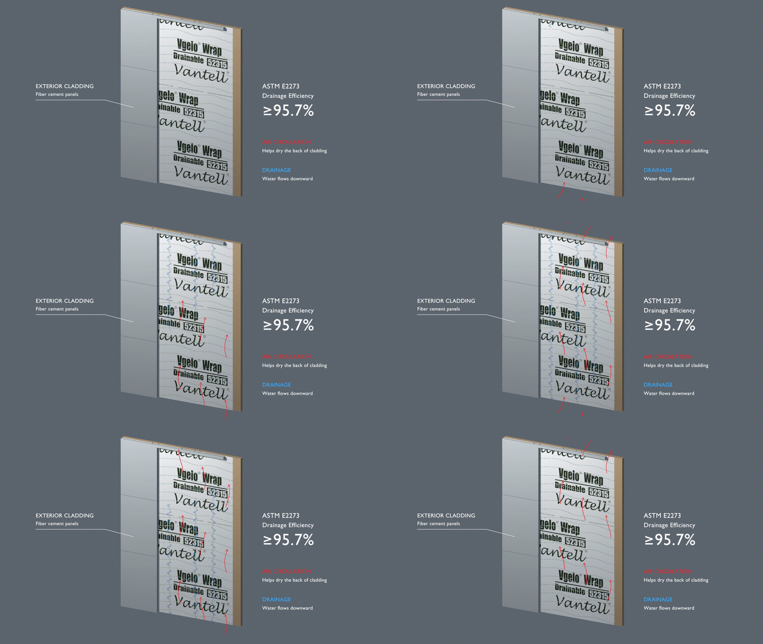
Drainage should not be confused with ventilation. A small structured drainage space can provide an effective path for bulk-water removal without necessarily delivering the air-exchange rates associated with a deliberately vented or ventilated rainscreen.
Water Application Rate Changes the Result
One of the more important aspects of the IIBEC research is that the authors did not evaluate drainage gap size in isolation.
They also examined how the amount of water introduced into the wall affects measured drainage efficiency.
The ASTM E2273 test method uses a water application rate of approximately 0.106 L/min.
The full-scale study evaluated three conditions:
- approximately 0.053 L/min, or 50% of the standard flow;
- approximately 0.106 L/min, the standard flow; and
- approximately 0.212 L/min, or twice the standard flow.
When the application rate was reduced by half, drainage efficiency dropped to approximately 91%.
When the standard flow rate was doubled, however, drainage efficiency changed very little.
The authors attributed this behavior largely to the influence of head pressure.
As more water accumulates at the top of a constrained drainage path, the water itself helps displace the water below it.
At lower application rates, that displacement effect becomes weaker.
The study therefore raises an important limitation of standardized drainage testing: the reported efficiency is influenced not only by drainage-space geometry but also by the hydraulic conditions created by the test.
The authors further observed that real-world water infiltration behind many types of cladding may occur at lower rates than the standard ASTM E2273 application rate.
Their conclusion was therefore not that ASTM E2273 is without value, but that a drainage-efficiency percentage should not be treated as a complete description of real-world moisture behavior.
What Happens to Water That Does Not Drain?
No practical drainage assembly releases 100% of applied water immediately.
Some moisture remains as films or droplets attached to drainage surfaces, while absorptive materials can retain additional water.
In the IIBEC study, the WRBs and HDPE battens were nonabsorptive. Fiber cement therefore became the primary absorptive material at the drainage interface.
The benchtop assemblies retained approximately 5% of the applied water.
Of this undrained portion, moisture absorbed by the fiber cement represented between approximately 18% and 85% depending on the replicate.
Interestingly, the fiber cement panels installed over the 1.5 mm drainage wrap absorbed less water than the panels installed over the 10 mm battens in the benchtop evaluations.
The researchers attributed this unexpected result partly to differences in water distribution.
With the 10 mm battens, water tended to flow through a comparatively concentrated area corresponding to the application location, producing repeated exposure of a limited portion of the fiber cement panel.
The drainage wrap dispersed water into smaller, discrete streams across the interface.
The finding illustrates an important point:
Drainage performance is influenced not only by cavity depth, but also by how water is distributed, transported, stored, and released within the interface.
Drainage and Drying Are Different Functions
A larger drainage cavity is often assumed to provide significantly better drying.
That assumption is only valid when the cavity is also configured to achieve meaningful air exchange.
The paper distinguishes between drainage walls and rainscreen walls.
A drainage wall primarily removes water. A vented or ventilated rainscreen combines drainage with substantially greater air exchange and, in some configurations, greater moderation of pressure differences across the cladding.
The authors note that typical unvented drainage cavities may experience only about 1 to 5 air changes per hour (ACH), while vented and deliberately ventilated rainscreens can achieve substantially higher rates.
A nominal 10 mm gap therefore should not automatically be assumed to behave like a properly ventilated rainscreen simply because it is deeper.
What the Hygrothermal Modeling Found
To investigate long-term wetting and drying behavior, the researchers conducted five-year simulations using WUFI Pro 7.0 for 15 North American climate locations.
The modeled wall included fiber cement cladding, either a 1.5 mm or 10 mm drainage space, polyolefin housewrap, plywood sheathing, insulated wood framing, and interior gypsum.
The researchers assumed:
- 1 ACH ventilation for the 1.5 mm drainage space; and
- 20 ACH ventilation for the 10 mm space.
The paper specifically notes that the 20 ACH assumption for the 10 mm cavity was generous because walls constructed only to satisfy basic code requirements do not necessarily include the vent openings required to achieve this rate.
Moisture infiltration was modeled according to ASHRAE Standard 160 using a total wind-driven rain fraction of 1%, divided between the WRB and the interior surface of the fiber cement.
The simulations indicated that the presence of moisture infiltration and the exterior climate generally had a greater influence on wall performance than gap depth and assumed ventilation rate alone.
The researchers found no evidence of long-term moisture accumulation in other modeled material layers under the conditions evaluated.
Climate Still Matters
The influence of gap dimension became more pronounced in marine and cool-humid climates receiving more than approximately 1,000 mm of annual rainfall.
Under those conditions, the results supported the use of larger drainage spaces together with higher ventilation rates.
That distinction is important.
The study should not be interpreted as evidence that a 1.5 mm drainage layer can replace every conventional rainscreen cavity.
Instead, it demonstrates that:
- drainage efficiency;
- drainage-space depth;
- ventilation;
- moisture storage;
- cladding absorption; and
- drying potential
are related but distinct aspects of wall performance.
A Further Design Question: Drainage Behind Exterior Insulation
The paper also raises an important issue that goes beyond conventional cladding cavities.
In walls with exterior insulation, a drainage interface can exist between the insulation and the WRB even when a separate rainscreen cavity is provided farther outboard.
This creates a design challenge.
If every drainage layer were required to use a large and highly ventilated cavity, the space between exterior insulation and the WRB could conflict with the thermal function of the insulation system.
The authors therefore identify an important role for smaller drainage spaces at the insulation-to-WRB interface: allowing water to drain while avoiding an unnecessarily large cavity at a location where thermal continuity is important.
In their conclusion, the researchers state that a 1.5 mm space can effectively serve this drainage objective, while also noting that further research is needed to better understand drainage and drying in spaces that are thermally isolated from the exterior rainscreen cavity.
This reinforces a broader principle:
Drainage-space geometry should be selected according to the function required at a particular layer of the wall rather than by applying one cavity dimension universally to every enclosure configuration.
Drainage Wall vs. Ventilated Rainscreen
This distinction is particularly important when specifying modern drainable WRBs.
A structured WRB can create a pathway for bulk water to move downward behind cladding.
That does not automatically create the high ventilation rates or pressure moderation associated with a deliberately ventilated rainscreen.
For many wall assemblies, efficient drainage of incidental water may be the primary objective.
For others—particularly highly exposed buildings or construction in wet marine and cool-humid climates—the designer may require both drainage and substantial cavity ventilation.
The appropriate solution therefore depends on factors including:
- climate and annual rainfall;
- wind-driven rain exposure;
- cladding type;
- wall configuration;
- moisture sensitivity of adjacent materials;
- expected leakage conditions;
- location of the primary drainage plane; and
- whether the design objective is drainage alone or drainage plus ventilation.
What This Means for Drainable WRBs
The broader significance of the IIBEC research is that drainage performance should not be evaluated solely by the nominal depth of a cavity.
A 10 mm cavity has clear advantages where the wall design calls for a true vented or ventilated rainscreen.
But where the objective is to establish an effective pathway for bulk-water drainage directly adjacent to the WRB, the research demonstrates that much smaller engineered drainage spaces can achieve high drainage efficiency.
This is the same general moisture-management function addressed by Vantell VWD52315 Drainable Housewrap.
VWD52315 incorporates an integrated 1.5 mm drainage structure, creating a drainage pathway as part of the WRB system rather than relying solely on a separate furring layer to establish drainage immediately adjacent to the membrane.
VWD52315 has separately demonstrated a drainage efficiency of ≥95.7% in accordance with ASTM E2273.
This Vantell result is independent of the IIBEC study.
The paper identifies its 1.5 mm test material only as a commercially available drainage wrap and does not identify Vantell VWD52315 as the product evaluated.
Vantell therefore does not present the IIBEC research as product-specific validation. Rather, the study provides useful independent building-science context for understanding why drainage performance should be evaluated through actual water-management behavior rather than nominal gap depth alone.
What Should Designers Take Away?
The most useful conclusion from the study is not that 1.5 mm is universally better than 10 mm—or that 10 mm is unnecessary.
Instead, wall drainage should be treated as a system-level moisture-management problem.
Important questions include:
- How much water is likely to penetrate the cladding?
- Where will that water reach the drainage plane?
- Is the drainage pathway continuous?
- Can water exit freely at the bottom of the assembly?
- How absorptive are the cladding and adjacent materials?
- What happens to water that does not drain immediately?
- How effectively can the assembly dry after wetting?
- Does the climate justify additional cavity ventilation?
- Where is the primary drainage plane located in relation to exterior insulation?
- How are windows, doors, penetrations, flashings, and terminations integrated with the WRB?
A nominal cavity dimension alone cannot answer these questions.
Performance, Not Gap Size Alone
Modern drainable WRBs reflect a broader shift in building-envelope design: moving from assumptions based only on geometry toward verification of actual water-management performance.
In the 2025 IIBEC study, a 1.5 mm drainage wrap and a conventional 10 mm batten-created drainage space produced remarkably similar ASTM E2273 drainage efficiencies behind the fiber cement cladding assemblies that were tested.
At the same time, the research shows why drainage efficiency alone cannot describe the complete moisture behavior of a wall.
Water application rate, hydraulic head, material absorption, climate, moisture infiltration, cavity ventilation, and drying potential all influence enclosure performance.
For many assemblies, an engineered small-gap drainage layer can provide an effective and construction-efficient method of managing incidental bulk water.
Where substantial cavity ventilation and enhanced drying are required—particularly in demanding marine or cool-humid climates—a larger and properly ventilated rainscreen cavity may still be the more appropriate design.
The key is to specify the drainage strategy according to the performance required at each layer of the wall rather than assuming that bigger automatically means better.
Source and Further Reading
This article discusses research by:
M. Steven Doggett, PhD; Jarrett Davis, AMB, CGP, CDT, LEED AP BD+C; and Mathew Congleton
“Drainage Efficiencies of Fiber Cement Panels.”
2025 IIBEC Building Enclosure Symposium, October 26–28, 2025.
View the research page at Built Environments
View the 2025 IIBEC Building Enclosure Symposium Proceedings
The research discussed in this article is independent third-party work and does not constitute an endorsement of Vantell or any Vantell product by the authors, Built Environments, or IIBEC. Vantell product performance data referenced in this article comes from separate product testing.